Having browsed through half the Internet without finding any decent documentation on how to do this, I gave up on Google and put together something myself. Hopefully it can be useful for other networking students.
I’m doing a lab for Cisco CCNP ROUTE where you’re supposed to set up OSPF over a Frame Relay (NBMA) hub-and-spoke topology with a headquarter and two remote sites. All subinterfaces must be configured as point-to-point. This is how you configure the Frame Relay part.
Topology:
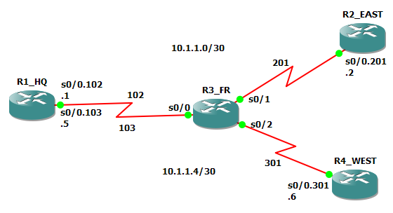
- DLCI 102 and 201 connecting R1_HQ and R2_EAST.
- DLCI 103 and 301 connecting R1_HQ and R4_WEST.
- R3_FR provides clocking signals (DCE) to the connected Frame Relay routers (DTE).
Configuration of the Frame Relay switch, R3_FR:
frame-relay switching

 interface Serial0/0

 bandwidth 64

 no ip address

 encapsulation frame-relay IETF

 no ip route-cache

 clock rate 64000

 frame-relay intf-type dce

 frame-relay route 102 interface Serial0/1 201

 frame-relay route 103 interface Serial0/2 301

 interface Serial0/1

 bandwidth 64

 no ip address

 encapsulation frame-relay IETF

 no ip route-cache

 clock rate 64000

 frame-relay intf-type dce

 frame-relay route 201 interface Serial0/0 102

 interface Serial0/2

 bandwidth 64

 no ip address

 encapsulation frame-relay IETF

 no ip route-cache

 clock rate 64000

 frame-relay intf-type dce

 frame-relay route 301 interface Serial0/0 103
Configuring the R1_HQ router:
interface Serial0/0

bandwidth 64

no ip address

encapsulation frame-relay IETF

interface Serial0/0.102 point-to-point

ip address 10.1.1.1 255.255.255.252

frame-relay interface-dlci 102

interface Serial0/0.103 point-to-point

ip address 10.1.1.5 255.255.255.252

frame-relay interface-dlci 103
Configuring the R2_EAST router:
interface Serial0/0

bandwidth 64

no ip address

encapsulation frame-relay IETF

interface Serial0/0.201 point-to-point

ip address 10.1.1.2 255.255.255.252

frame-relay interface-dlci 201
Configuring the R4_WEST router:
interface Serial0/0

 bandwidth 64

 no ip address

 encapsulation frame-relay IETF

 interface Serial0/0.301 point-to-point

 ip address 10.1.1.6 255.255.255.252

 frame-relay interface-dlci 301
HQ router can now ping both the EAST and WEST router.
Here’s how the Frame Relay switch see the topology:
R3_FR#show frame-relay route
Input Intf      Input Dlci      Output Intf     Output Dlci     Status
Serial0/0       102             Serial0/1       201             active
Serial0/0       103             Serial0/2       301             active
Serial0/1       201             Serial0/0       102             active
Serial0/2       301             Serial0/0       103             active
For more information check out “Comprehensive Guide to Configuring and Troubleshooting Frame Relay”:
http://www.cisco.com/en/US/tech/tk713/tk237/technologies_tech_note09186a008014f8a7.shtml
Similar services are also provided professionally through my Consulting Services.
Sharing is caring:


Leave a Reply